Frequently Asked Questions about Black Box ToolKit products and millisecond timing error

 Researchers,
academics and technical staff from around the world are equally
concerned about millisecond timing accuracy in psychology
experiments and often contact us with specific questions. By
analyzing trends, we have put together this FAQ that should help
answer many of your questions and allay any concerns you may have
about any of our products.
Researchers,
academics and technical staff from around the world are equally
concerned about millisecond timing accuracy in psychology
experiments and often contact us with specific questions. By
analyzing trends, we have put together this FAQ that should help
answer many of your questions and allay any concerns you may have
about any of our products.Why not scroll down to see some worked examples!
If you have a question that isn't covered, or would like to know more about a specific area, feel free to email us at: info@blackboxtoolkit.com.
General
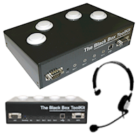
- What is the Black Box Toolkit v3 and why should I use it?
- What can I measure with the Black Box Toolkit v3?
- How common are conditional biases that affect presentation and response timing?
- Why do I need to check every paradigm? Can't I just benchmark the PC, Mac or Linux system the experiment is running on?
- Which academic journals are requesting that authors validate their timings?
- How can your software/Black Box ToolKit v3 get accurate timings when my experiment generator can't?
- Can I test the timing of my Mac or Linux based experiment? What about other platforms or equipment like MRI, EEG and eye trackers?
Using the Black Box ToolKit v3
- What's do the terms Host and Remote mean?
- How do I check whether visual and auditory stimuli are synchronized?
- How do I use the BBTK v3 Robotic Key Actuator to press keys on a laptop or response pad to check response timing?
- How do I use the BBTK v3 Robotic Key Actuator to make responses on an iPad, Android tablet or other touch screen device?
- How do I test the response latency of voice keys?
- How can I use video clips and obtain accurate timing?
- How do I check the timing accuracy of a visual priming or RSVP study?
- How can I use the BBTK v3 to check AOA timings with an eye tracker?
- How do I event mark stimulus or response activity on an EEG trace?
- How do I event mark complex stimulus, synchronization or response activity on an EEG trace?
- How do I use a MRI synchronization trigger pulse or reference signal in fMRI?
Correcting timing errors
- My chosen response device is adding to response timing. What should I do?
- How do I plot the absolute error and variability of my response device?
- I've found an error in the synchrony between my visual or auditory stimuli. How do I correct this?
- There is a synchronization error between my experiment and third party equipment (EEG, MEG, fMRI, eye tracker). How do I correct this?
- Should I look at whole system timing to improve my accuracy?
What's the best X? – The Curate's Egg*
- What's the most accurate experiment generator for presentation and response timing?
- Which brand/model or computer is the most accurate?
- What's best for visual presentation: a CRT, TFT or data projector?
- What's the best response device?
- I can connect my response device by either USB or serial. What interface is best?
- PC/MAC/Linux... Which is best?
- Soundcards... Which one should I buy?
- Which graphics card?
- Are faster multi-core processors better than
slower ones?
*What does the term "Curate's Egg" mean?
Technical
- How does the BBTK v3 connect to the host PC?
- Environmental Considerations
- Will your BBTK v3 work in our MRI scanner room?
- Is there a Mac/Linux version of the software? Is there an API?
- We've built some custom response equipment. How do we link to the TTL interfaces offered by the BBTK v3?
- How many screen regions can I monitor at once?
- How do I adjust the sensitivity of the BBTK v3 sensors?
- Can I use the BBTK v3 with third party experiment generators or software I wrote myself?
- How do I link the BBTK v3 up to my MRI scanner sync pulse so that I can relate presentations to actual acquisitions?
Bench test equipment comparisons
- Can I use the BBTK v3 like a traditional digital oscilloscope?
- Can I use the BBTK v3 like a traditional pulse/function generator?
- Can I do what the Black Box ToolKit v3 does with a digital oscilloscope and signal generator?
- What's the typical sampling rate of the Black Box Toolkit v3?
Training, demos & consultancy services
- Our department would like you to come and give a talk. Would you be willing to do this? What about training?
- We'd like to integrate some best practice guidance into the way we teach undergraduates in the use of experiment generators. Could you advise us?
- Our study is time critical and we need to have validated results together with independent timing certification. Do you offer a consultancy service?
Contacting us & ordering
General
What is the Black Box ToolKit v3 and why should I use it?
The Black Box ToolKit v3 is a device that lets you quickly and easily check your own millisecond timing accuracy in terms of stimulus presentation accuracy; stimulus synchronization accuracy; and response time accuracy.
 Researchers
within the behavioral sciences regularly make use of
computer-based paradigms. Most assume that the computer
accurately presents stimulus materials and records responses as
programmed. However research has shown this expectation is often
misplaced. Presentation, synchronization and response timing
errors can be caused by many factors. Whether you make use of a
commercial experiment generator or write custom software, you
are likely to succumb to such errors. Inconsistent timing can
lead to spurious conditional effects, poor replicability and bad
science.
Researchers
within the behavioral sciences regularly make use of
computer-based paradigms. Most assume that the computer
accurately presents stimulus materials and records responses as
programmed. However research has shown this expectation is often
misplaced. Presentation, synchronization and response timing
errors can be caused by many factors. Whether you make use of a
commercial experiment generator or write custom software, you
are likely to succumb to such errors. Inconsistent timing can
lead to spurious conditional effects, poor replicability and bad
science.
 The
ToolKit has been specifically developed to help researchers
address timing issues related to their own paradigms running on
their own hardware. The BBTK v3 operates as a virtual human
programmed to respond to stimulus presentations and generate
appropriate responses very accurately. It can step through your
whole experiment as if it was a human participant. Typically
external sensors are hooked up to a second PC, Mac or Linux box
to detect stimulus presentations. An output interface is used to
feed a response into the paradigm under test. The BBTK v3
measures the timing of all stimulus, synchronization and
response events extremely accurately, allowing the researcher to
compare timing measured by their own equipment with the actual
real world timings. The BBTK v3 can also work with up to 20 I/O
TTL lines when used in fMRI studies, for EEG event
marking/triggering or eye tracking.
The
ToolKit has been specifically developed to help researchers
address timing issues related to their own paradigms running on
their own hardware. The BBTK v3 operates as a virtual human
programmed to respond to stimulus presentations and generate
appropriate responses very accurately. It can step through your
whole experiment as if it was a human participant. Typically
external sensors are hooked up to a second PC, Mac or Linux box
to detect stimulus presentations. An output interface is used to
feed a response into the paradigm under test. The BBTK v3
measures the timing of all stimulus, synchronization and
response events extremely accurately, allowing the researcher to
compare timing measured by their own equipment with the actual
real world timings. The BBTK v3 can also work with up to 20 I/O
TTL lines when used in fMRI studies, for EEG event
marking/triggering or eye tracking.
Easy-to-use software allows for graphical control of monitored stimulus events, synchronization triggers and generated responses. A virtual 20 channel scope is used for analysis. Cursors allow measurement of timing between any two points and each events onset, offset and duration is shown in detail in a spreadsheet view. Top
What can I measure with the Black Box Toolkit v3?
 The
Black Box ToolKit v3 offers various sensors that can be attached
externally to a second computer system running an experiment.
These sensors detect when a visual stimulus is displayed, audio is
played, a TTL signal or TTL trigger is received, or when a human
presses a remote response button. All testing can be done without
modifying your experiment, in situ, on your own equipment by
virtue of the use of external sensors. Three versions of the BBTK
v3 are available: Entry (12 channel), Pro (20 channel) and Elite
(36 channel). They differ in the number of channels available and
the number of sensors supplied is specific to the package
purchased.
The
Black Box ToolKit v3 offers various sensors that can be attached
externally to a second computer system running an experiment.
These sensors detect when a visual stimulus is displayed, audio is
played, a TTL signal or TTL trigger is received, or when a human
presses a remote response button. All testing can be done without
modifying your experiment, in situ, on your own equipment by
virtue of the use of external sensors. Three versions of the BBTK
v3 are available: Entry (12 channel), Pro (20 channel) and Elite
(36 channel). They differ in the number of channels available and
the number of sensors supplied is specific to the package
purchased.
A summary of all the channels and features offered is shown below (36 channel Elite model):
- Opto-detectors: Up to 4 screen regions can be monitored for visual stimuli
- BBTK microphones: Up to 2 high performance digital mics for timing auditory stimulus presentations
- BBTK sounders: Up to 2 high performance digital tone generators for triggering your own voice keys
- Active Switch Closure: Up to 4 Active Switch Closure leads for triggering buttons/keys on your own devices a though a human participant had pressed them
- BBTK response pad: A 4 button BBTK response pad for accepting responses from human participants. Active Switch Closure leads from the pad allow you to trigger up to 4 buttons/keys on your own response device
- TTL input: Up to 10 TTL input channels/TTL triggers allow you to time TTL signals sent from external equipment, e.g. fMRI, EEG, eye trackers etc.
- TTL output: Up to 10 TTL output channels/TTL triggers allow you to event mark individual stimuli or response events
- Robotic Response Key Actuator: The RKA can press keys on your own response devices, e.g. laptop keys, response pads, Android tablets, iPads, touch screen phones etc.
The BBTK v3 can be used to test the timing of virtually any experimental paradigm by acting as a highly accurate virtual human pre-programmed to respond to stimuli and automatically step through your experiment. The exact timing of any event, on any sensor or response channel, is logged with sub-millisecond accuracy enabling you to quickly determine real world accuracy.
Where required it can even take over all presentation and response timing duties from your own hardware meaning you can be sure of sub-millisecond presentation and response timing in situations that are traditionally impossible, e.g. video clip presentation and response timing. Top
How common are conditional biases that affect presentation and response timing?
 Unfortunately
they have existed in every paradigm we have looked at regardless
of platform, operating system, or whether a commercial
experiment generator has been used or not. In all cases the
researcher has been unaware of the magnitude of presentation,
synchronization, or response biases. More worryingly on many
occasions there has been a conditional bias caused by the
equipment itself. For example in cross modal studies it is
common for trials where audio is present to have markedly
different response timing characteristics. This can account for
apparently statistically significant experimental results that
lead to spurious conclusions.
Unfortunately
they have existed in every paradigm we have looked at regardless
of platform, operating system, or whether a commercial
experiment generator has been used or not. In all cases the
researcher has been unaware of the magnitude of presentation,
synchronization, or response biases. More worryingly on many
occasions there has been a conditional bias caused by the
equipment itself. For example in cross modal studies it is
common for trials where audio is present to have markedly
different response timing characteristics. This can account for
apparently statistically significant experimental results that
lead to spurious conclusions.
The latest research also suggests that human participants are actually much faster processors of information than previously thought. In the case of vision Thurgood, Whitfield & Patterson, 2011, showed that humans could recognize the outlines of animals with 83% accuracy at exposure times of just one millisecond when using specialist presentation devices. This makes accurate presentation, synchronization and response timing even more critical.
In the majority of cases timing errors can be improved by use
of the Black Box ToolKit v3. Either experimental parameters can
be altered or post-hoc statistical manipulation can be carried
out (where response data has a low variability and constant
absolute error). Top
Why do I need to check every paradigm? Can't I just benchmark the PC, Mac or Linux system the experiment is running on?
 Unfortunately
not. Benchmarking a PC, Mac or Linux system in traditional
terms, e.g. to obtain a MIPS rating, doesn't tell you how the
system will perform in the real world. In short, it is a
synthetic benchmark. In much the same way benchmarking one
paradigm doesn't tell you how another will perform on the same
hardware even if the two paradigms appear similar. Any settings
change in the experiment generator, or third party software, is
also likely to have an effect. What is more it is hard to
account for human error on the part of the experimenter when
creating experiments without independently and objectively
checking presentation and response timings. Often presentation,
synchronization and response errors are undetectable by the
experimenter, but go on to affect the perceptions and
performance of real participants. Top
Unfortunately
not. Benchmarking a PC, Mac or Linux system in traditional
terms, e.g. to obtain a MIPS rating, doesn't tell you how the
system will perform in the real world. In short, it is a
synthetic benchmark. In much the same way benchmarking one
paradigm doesn't tell you how another will perform on the same
hardware even if the two paradigms appear similar. Any settings
change in the experiment generator, or third party software, is
also likely to have an effect. What is more it is hard to
account for human error on the part of the experimenter when
creating experiments without independently and objectively
checking presentation and response timings. Often presentation,
synchronization and response errors are undetectable by the
experimenter, but go on to affect the perceptions and
performance of real participants. Top
Which academic journals are requesting that authors validate their timings?
 Currently
most journals are not requesting that authors formally specify
that they have tested the timing characteristics of their study.
However this will be changing in the near future with many
journals setting the trend by requesting that authors submit
their software, scripts and data for inclusion within a
repository. The current focus on replication across the field is
testament to the fact that journal editors and reviewers are
tightening their criteria for publication. Whilst we accept that
academics follow best endeavors, on many occasions it is useful
to know the timing limits on a given study and how the author
verified timing accuracy.
Currently
most journals are not requesting that authors formally specify
that they have tested the timing characteristics of their study.
However this will be changing in the near future with many
journals setting the trend by requesting that authors submit
their software, scripts and data for inclusion within a
repository. The current focus on replication across the field is
testament to the fact that journal editors and reviewers are
tightening their criteria for publication. Whilst we accept that
academics follow best endeavors, on many occasions it is useful
to know the timing limits on a given study and how the author
verified timing accuracy.
In addition within academic publications it is often difficult
to unpick the contribution to timing that may have come from an
uncontrolled source. By testing the timing of computer-based
paradigms this also helps ensure that successful replications
are more likely. In fields such as priming there is still active
debate on the direction of some findings and in general
researchers are seeking out ever smaller and smaller differences
between conditions. In both cases self-validation of timing is
crucial in order to avoid statistically significant results that
are purely due to equipment variation. Top
How can your Black Box ToolKit v3 obtain accurate timings when my experiment generator can't?
 The
Black Box ToolKit v3 is based around a 32 bit ARM CPU, like the
one in most iPhones and Android handsets and has 2 MB of onboard
RAM for storing its firmware and settings and 8 MB of RAM for
storing timing data.
The
Black Box ToolKit v3 is based around a 32 bit ARM CPU, like the
one in most iPhones and Android handsets and has 2 MB of onboard
RAM for storing its firmware and settings and 8 MB of RAM for
storing timing data.Once you have told it what stimuli to respond to it will
automatically step through your whole experiment and timestamp
any stimulus events, synchronization markers and responses with
sub-millisecond accuracy. This is done independently of the PC
which hosts the BBTK v3 as its USB link is only used for
programming and subsequently uploading the data at the end of a
sequence. Once running the BBTK v3 operates completely
independently. The Black Box ToolKit can be thought of as a
small computer dedicated to helping you improve your timing
accuracy. Top
Can I test the timing of my Mac or Linux based experiment? What about other platforms or equipment like MRI, EEG and eye trackers?
Yes. You can test the timing characteristics of any experiment on any platform. This is because the kit behaves like a virtual human and operates non-invasively. It has a range of external sensors, response mechanisms and TTL input/TTL triggers and output lines which hook up to your own equipment to measure presentation, synchronization and response accuracy. Top
Using the Black Box ToolKit v3
What do the terms Host and Remote mean?
The term Host is used to refer to the Microsoft Windows based PC that has the Black Box ToolKit v3 physically plugged into its USB port and runs our PC Software (XP, Windows 7 or Windows 8). This PC controls the BBTK and analyses data. It could be a PC desktop, laptop or netbook. By using VMWare, Parallels, VirtualBox or Boot Camp this also lets you control the BBTK from other platforms. In addition by using the BBTK v3 API you can also control and analyze data using your own custom written software, e.g. MATLAB, PsychoPy etc.
Whereas the term Remote is used to refer to the PC/MAC/Linux
system that is running the experiment you are interested in
checking the timing of. Remember that the Remote could also
refer to other specialist equipment, e.g. MRI scanner, EEG
machine, eye tracker etc. Top
How do I check whether visual and auditory stimuli are synchronized?
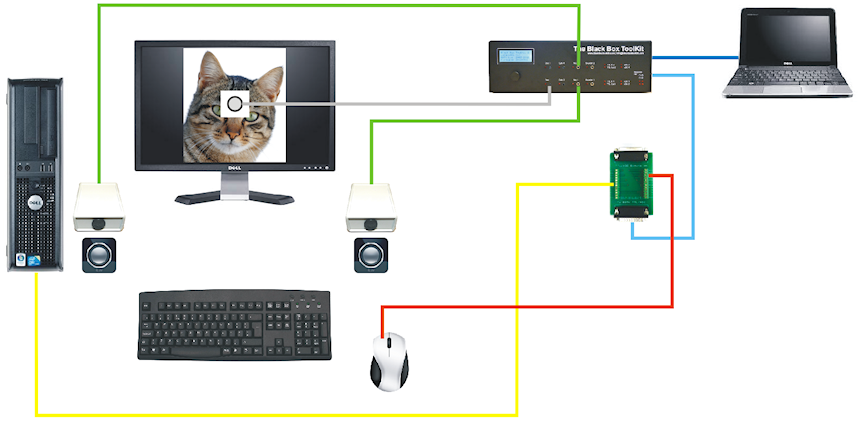
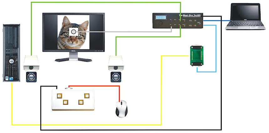
To check the synchrony of visual and auditory stimuli you would attach one or more opto-detectors to your remote screen, i.e. the computer running the experiment (shown in grey below). Then place one or more BBTK v3 microphones next to your remote speakers (green). To provide a baseline you could also attach a TTL lead from the parallel port of your remote PC to the BBTK v3 breakout board (yellow). If your PC does not have a parallel port you could use a BBTK USB TTL event marking module instead. To utilize this TTL synch signal you would program your experiment generator script to output a TTL signal at the onset of the presentation of the visual stimulus. An Active Switch Closure (ASC) lead could be wired from the breakout board of the BBTK (light blue) to the left mouse button of your remote PC (red) so as to trigger a response when each stimulus image is detected.
The collection of timing data and generation of responses is controlled by a second host PC/Laptop/Netbook that is connected to the BBTK via USB (blue). The Digital Stimulus Capture And Response (DSCAR) module of the BBTKv3 PC Software would be run from this second host PC in order to detect visual stimuli and make responses. In this example DSCAR has been instructed to respond after 300mS by pressing the left mouse button using an ASC lead (red).
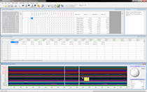
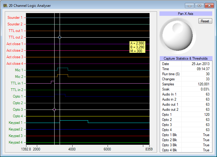
Once the BBTK has automatically stepped through your whole experiment, timing data will be presented for analysis. One spreadsheet view displays raw timing data whilst a second displays changes across up to 36 channels, e.g. visual stimulus onset, offset and duration in milliseconds. A graphical 20 Channel Logic Analyzer enables you to compare the timings of any events by means of two draggable measurement cursors.
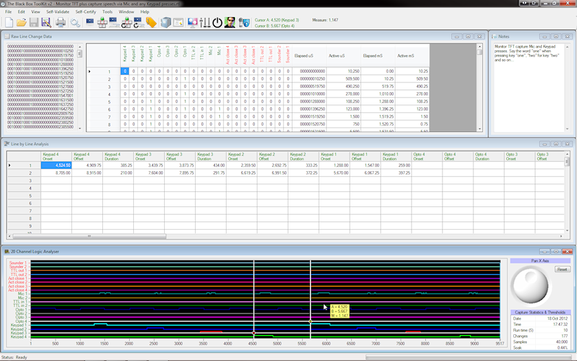
In this example we can see that the TTL signal from the remote PC running the experiment appears on TTL in 1 before the onset of the visual stimuli on Opto 1. The onset of both should be synchronized and any difference between the two is likely to be due to the input lag of the display device. That is, the inherent delay between requesting an image be displayed and when it physically appears. This delay is usually caused by the display devices electronics and any image processing. On the same trace we can see that the two mics detected the leading edge of a stereo tone later than the onset of the visual presentation. Such delays can be caused by sound card startup latency where the intended tone appears at the speakers much later than requested due to the sound cards electronics. Act close 1 shows when the BBTK v3 generated a response relative to the onset of the visual stimulus image. In this case a yellow tooltip shows that the true RT is 300 ms.
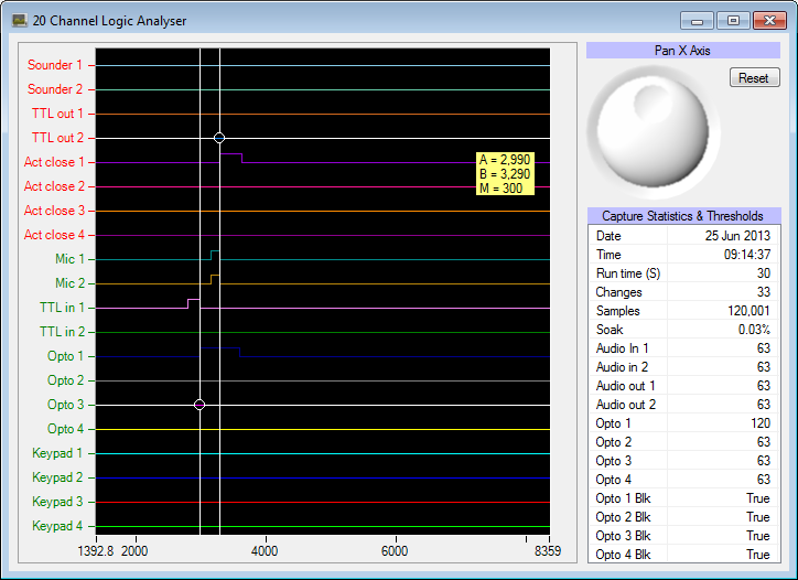
By comparing the true RT generated by the BBTK against that
recorded by the experiment generator it is possible to calculate
the level of response timing error in the paradigm. Top
How do I use the BBTK v3 Robotic Key Actuator to press keys on a laptop or response pad to check response timing?
The Robotic Key Actuator (RKA) is designed to press a key on a response device without having to dismantle it to physically wire an Active Switch Closure (ASC) lead from the BBTK v3. Once calibrated the RKA is consistent to around 1-2 ms when pressing keys. The RKA has an adjustable plunger that can be moved either horizontally or vertically to enable perfect positioning and a foam pad to provide cushioning for your response device.
In the example shown the RKA is pressing the space bar on a
Netbook keyboard in response to a visual stimulus detected on an
opto-detector (shown in grey below). The RKA is controlled via a
special trigger lead (black) from the breakout board and is
activated by a TTL Out 1 signal from the BBTK v3 that tells it
when to press and for how long.
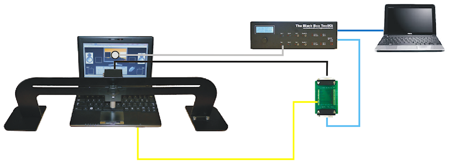
To provide a baseline you could also attach a TTL lead from the parallel port of the remote laptop/PC to the BBTK breakout board (yellow). If your PC does not have a parallel port you could use a BBTK USB TTL event marking module instead. To utilize the TTL synch signal wire you would program your experiment generator script to output a TTL signal at the onset of the presentation of a visual stimulus. The breakout board itself is connected to the BBTK via a 25-way cable (light blue).
The collection of timing data and generation of responses is
controlled by a second host PC/Laptop/Netbook that is connected
to the BBTK v3 via USB (blue). The Digital Stimulus Capture And
Response (DSCAR) module of the BBTK PC Software would run from
this second host PC in order to detect stimuli and make
responses with known RTs. Once the BBTK v3 has automatically
stepped through your whole experiment, timing data would be
presented for analysis. To calculate the RT error introduced by
your response device you would compare the RT recorded by your
experiment generator with the true RT generated by the BBTK v3.
Top
How do I use the BBTK v3 Robotic Key Actuator to make responses on an iPad, Android tablet or other touch screen device?
In addition to being able to press keys on your own response devices the Robotic Key Actuator (RKA) can also make responses on capacitive touch screen hardware. This is accomplished using a piece of high density electroconductive foam which is grounded to the breakout board (shown in green below).
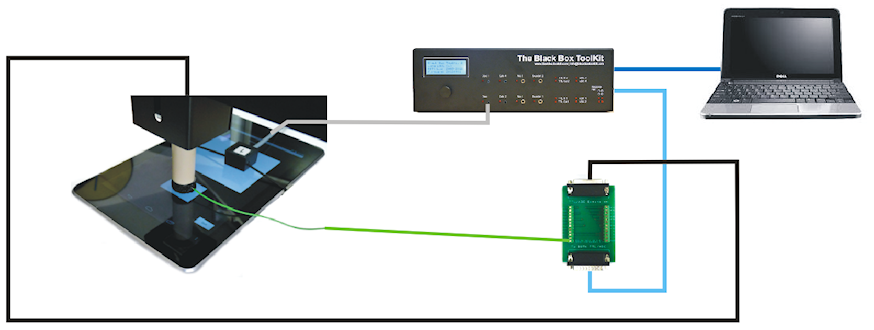
Once calibrated and a small air gap set, the RKA is consistent to around 1-2 ms when registering touches and releases. The RKA has an adjustable plunger which can be moved either horizontally or vertically to enable perfect positioning. The electroconductive foam pad also provides cushioning for your touch screen device.
In the example shown the RKA is touching the screen in response to a visual stimulus detected on an opto-detector (grey). The RKA is controlled by a special trigger lead (black) from the breakout board and is activated by a TTL Out 1 signal from the BBTK v3 that tells it when to press and for how long. The breakout board itself is connected to the BBTK v3 via a 25 way cable (light blue).
The collection of timing data and generation of responses is
controlled by a second host PC/Laptop/Netbook that is connected
to the BBTK v3 via USB (blue). The Digital Stimulus Capture And
Response (DSCAR) module of the BBTK v3 PC software would run
from this second host PC in order to detect stimuli and make
responses with known RTs. Once the BBTK v3 has automatically
stepped through your whole experiment, timing data would be
presented for analysis. Top
How do I test the response latency of voice keys?
One of the few reliable ways to test the response latency of a voice key is to use a TTL signal/TTL trigger from an experiment generator to indicate when it is ready to accept a response and then to generate an independent tone using a sounder. In the example shown below a TTL signal could be sent from the experiment generator into TTL In 1 (shown in yellow below) of the BBTK v3 via the breakout board. Using Digital Stimulus Capture And Response (DSCAR) you could construct a sequence that triggered on every TTL In 1 signal and in response generated a tone after 300 ms using a BBTK v3 Sounder (orange). This tone should trigger the experiment generators voice key (black) and register a RT of 300 ms should everything be working correctly. Any deviation from the intended true RT of 300 ms is likely to be due to the latency of the voice key hardware and detection routine within the experiment generator software.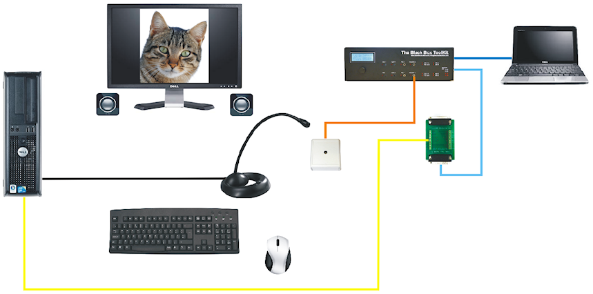
The collection of timing data and generation of responses is controlled by a second host PC/Laptop/Netbook that is connected to the BBTK v3 via USB (blue). Once the BBTK v3 has automatically stepped through your whole experiment, timing data would be presented for analysis. To check timings you would use the 20 Channel Logic Analyzer to confirm that each tone was generated on Sounder 1 300 ms after the onset of the TTL in 1 signal/TTL trigger from the experiment generator as shown below.

To automate the process of checking RTs and ISIs you could copy
and paste the Line By Line Analysis spreadsheet into Microsoft
Excel and enter a formula rather than drag the measurement
cursors around to check individual timings. Top
How can I use video clips and obtain accurate timing?
Traditionally experiment generators are extremely poor at timing when a video stimulus is playing. Using the BBTK response pad together with our Digital Stimulus Capture (DSC) software can help you obtain sub-millisecond accurate presentation and response timings. In this scenario the experiment generator is only presenting the video and all timing duties are taken over by the BBTK.
To achieve this level of accuracy you would use a video editor to superimpose a white 32x32 pixel event marker block at the start of each scene you were interested in. Other frames should have a black block at the same position so that they don't activate the BBTK opto-detector. Typically event markers are placed at the bottom corner of a video so that the opto-detector can be covered up by a custom made secondary frame obscuring the bottom 32 pixels of the monitor.
In the example shown below an opto-detector is attached to the screen to detect the event marker (shown in grey below). To provide a baseline you could also attach a TTL lead from the parallel port of the remote laptop/PC to the BBTK breakout board (yellow). If your PC does not have a parallel port you could use a BBTK USB TTL event marking module instead. To utilize this TTL synch signal wire you would program your experiment generator script to output a TTL signal/TTL trigger at the onset of the presentation of a visual stimulus.
The breakout board itself is connected to the BBTK v3 via a 25-way cable (light blue). Two BBTK mics could be placed next to your speakers to timestamp any audio (green). Finally to accept responses a 4 button BBTK response pad is connected to the main unit (black) and an Active Switch Closure (ASC) lead tacked to your own response device button (red). When a key is pressed on the BBTK response pad your own response device would be simultaneously triggered as though a button on it had been pressed.
When your experiment was complete you would use the 20 Channel Logic Analyzer to check for the occurrence of the white event marker on the scenes you were interested in (Opto 1). You could then use the cursors to measure the RT between the appearance of the reference block and a response button being pressed on Keypad 1 (300mS in this example). Any sounds played by the video would be shown on Mics 1 and 2.
If you wanted to check for TFT monitor input lag, or the lag between when the experiment generator thought it had correctly event marked the desired frames, you would check the sync of the TTL signal/TTL trigger sent to the BBTK v3 relative to those events (TTL in 1). For example, by subtracting the image onset from the TTL signal this gives a measure of the input lag and the inherent delay in your equipment and experiment generator.
Because your own response device would be triggered when you press a response key on the BBTK keypad (red) you could compare what your experiment generator recorded against the true RT recorded by the BBTK v3 to calculate response timing error.
To automate the process of determining true RTs you could copy and paste the Line By Line Analysis spreadsheet into Microsoft Excel and enter a formula to calculate each RT based on the onset of the videos event marker. Top
How do I check the timing accuracy of a visual priming or RSVP study?
For priming or RSVP studies you may wish to make use of multiple white opto-detector markers (up to 4 on the Pro and Elite models) so that you can detect each fixation, prime, mask and so on. If you don't want to activate an opto on a particular prime or mask you will need to have black event markers at all other opto locations as shown below.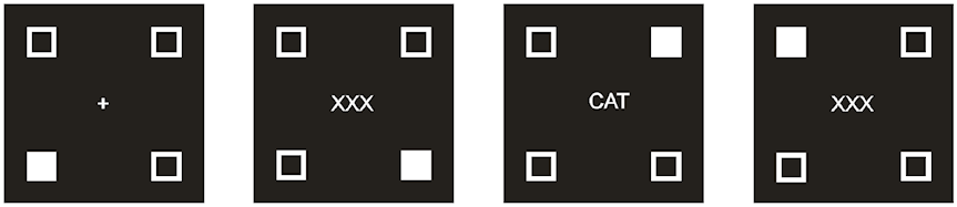
In this example opto 1 might be located to bottom left of your remote screen (fixation), opto 2 bottom right (mask), opto 3 top right (prime), opto 4 top left (mask). Where no optos should be triggered a black marker should be displayed. Typically this will be where the background is pure black and no event markers are displayed. By using all four optos you can monitor for the onset, duration and offset of each visual event on fixation frames, primes and masks.
To provide a baseline you could also attach a TTL lead from the
parallel port of your remote laptop/PC to the BBTK v3 breakout
board. If your PC does not have a parallel port you could use a
BBTK USB TTL event marking module instead. To utilize this TTL
synch signal wire you would program your experiment generator
script to output a TTL signal at the onset of the presentation
of a prime or mask. By subtracting the opto-detector onset from
the TTL signal onset this gives a measure of the input lag and
the inherent delay in your display equipment and experiment
generator. Top
How do I use the BBTK v3 to check AOA timings with an eye tracker?
The BBTK v3 has up to 20 TTL input and output channels or triggers that can be used to event mark stimuli, capture synchronization signals and record responses when performing eye tracking. This lets you check whether stimulus presentations and responses are temporally yoked to TTL AOA markers from your eye tracker – you can compare the events your experiment generator, or eye tracking hardware and software, timed against the true event timings measured by the BBTK v3.In the simple eye tracking scenario shown an experiment generator is presenting an image and playing a tone through a set of speakers. To check timing accuracy an opto-detector (shown in grey below) could be positioned on the remote screen so as to detect the onset and duration of each visual presentation. To record the timings of audio presentations one or more BBTK v3 microphones could be placed next to the remote speakers (green).
An AOA signal, or event marker, from your eye tracker could be fed into TTL In 1 of the BBTK v3 breakout board (yellow) in order to provide a gaze dependent reference. A second TTL trigger from your experiment generator could be connected to TTL In 2 (yellow). To utilize this second TTL signal you would program your experiment generator to output a TTL signal at the onset of each visual presentation. This would enable you to check the level of lag inherent in the display device and eye tracker being used. A third TTL signal (black) could be fed back into the eye tracking hardware from the BBTK v3 to act as an external event marker, e.g. to indicate when the speakers were producing sound.
An Active Switch Closure (ASC) lead could be wired from the breakout board of the BBTK v3 to the left button of the remote mouse (red) so as to trigger a response with a known RT when each stimulus image is detected, e.g. 300 ms. The breakout board itself is connected to the BBTK v3 via a 25 way cable (light blue).
![]()
The collection of timing data and generation of responses is
controlled by a second host PC/Laptop/Netbook that is connected
to the BBTK via USB (blue). The Digital Stimulus Capture And
Response (DSCAR) module of the BBTK v3 PC software is run from
this second host PC in order to detect stimuli, record TTL
events, act as an external event marking device and make
responses with known RTs. Once the BBTK v3 has automatically
stepped through your whole experiment, timing data will be
presented for analysis. By comparing the RT recorded by your
experiment generator against the true RT generated by the BBTK
v3, i.e. 300 ms, you will be able calculate response error. Top
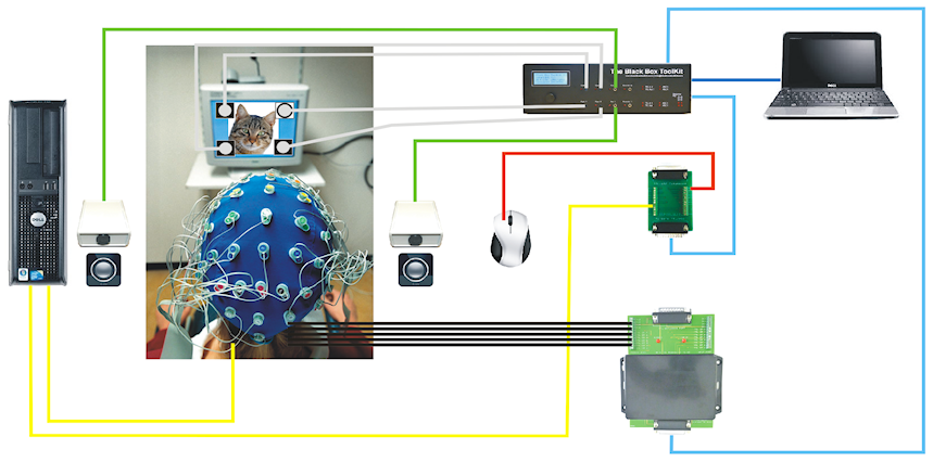
How do I event mark stimulus or response activity on an EEG trace?
The BBTK v3 has up to 10 TTL output channels/TTL triggers which can be used to event mark stimuli, synchronization triggers and responses on an EEG trace. For example, when a stimulus or patterns of stimuli are detected, a TTL event marker can be generated on any given channel. If the BBTK v3 is making a response with a known RT, a temporally yoked TTL marker can be generated to signify the onset of that event. This lets you compare the events your experiment generator, or EEG hardware and software, timed against the true event timings recorded by the BBTK v3.
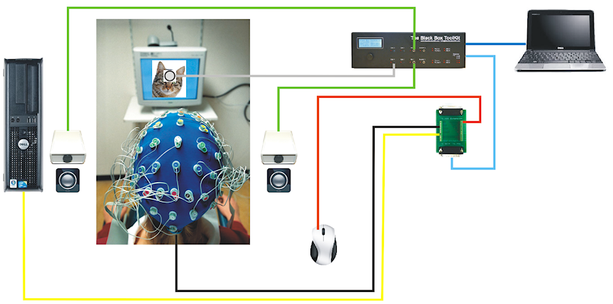
In the simple EEG scenario shown an experiment generator is presenting an image and playing a tone through the left or right speaker. To check the synchrony of a visual and auditory stimulus you could attach one or more opto-detectors to the remote screen (shown in grey below). Then place one or more BBTK microphones next to the remote speakers (green). To provide a baseline you could also attach a TTL lead from the parallel port of the remote PC to the BBTK v3 breakout board (yellow). If your PC does not have a parallel port you could use a BBTK USB TTL event marking module instead. To utilize this TTL synch signal wire you would program your experiment generator to output a TTL signal/TTL trigger at the onset of the presentation of the visual stimulus. An Active Switch Closure (ASC) lead could be wired to the breakout board of the BBTK (light blue) and then to the left mouse button of the remote PC (red) so as to make a response when each stimulus image is detected.
When the BBTK v3 physically detects a visual stimulus it could feed a TTL signal/event marker (black) into your EEG amplifier so as to mark the true onset. Alternatively when the BBTK v3 generated a response with a known RT by closing the switch on your mouse via an ASC lead, a simultaneous TTL marker/TTL trigger could be generated.
The collection of timing data and generation of responses is
controlled by a second host PC/Laptop/Netbook that is connected
to the BBTK v3 via USB (blue). The Digital Stimulus Capture And
Response (DSCAR) module of the BBTK v3 PC Software is run from
this second host PC in order to detect stimuli, synchronization
triggers and make responses with known RTs. Once the BBTK v3 has
automatically stepped through your whole experiment, timing data
will be presented for analysis. In addition to being able to
check stimuli timings, by comparing the RTs recorded by your
experiment generator against the true RTs generated by the BBTK
v3 you would also be able calculate response error. Top
How can I use the BBTK v3 to event mark complex stimulus or response activity on an EEG trace?
The BBTK v3 has up to 10 TTL output channels/TTL triggers which can be used to event mark stimuli, synchronization triggers and responses on an EEG trace. For example, when a stimulus or patterns of stimuli are detected, TTL event markers can be generated on specific channels tied to the stimulus location or type of stimulus. If the BBTK v3 is making a response with a known RT, a temporally yoked TTL marker/TTL trigger can be generated to signify the onset and duration of that event. This lets you compare the events your experiment generator, or EEG hardware and software, timed against the true event timings measured by the BBTK v3.
In the more complex EEG scenario shown an experiment generator is presenting a series of images and playing a tone through the left or right speaker. For example, four opto-detectors (shown in grey below) could be positioned on the remote screen so as to detect the onset and duration of four continuous frames in a priming study. At each position black/white markers would indicate the fixation frame, the mask, the prime and the backward mask. When each frame was detected by the BBTK v3 it would event mark each onset/duration on four separate TTL Out lines (black) which would be fed back into your EEG amplifier so as to mark the true onset/duration on one of four channels. In this case the four additional TTL lines/TTL triggers are provided by the 16 channel TTL expansion module connected to the BBTK v3 (light blue).
To time audio presentations you would place one or more BBTK v3 microphones next to the remote speakers (green). To provide a baseline you could also attach a TTL lead from the parallel port of the remote PC to the BBTK v3 breakout board (yellow). If your PC does not have a parallel port you could use a BBTK USB TTL event marking module instead. To utilize this TTL synch signal wire you would program your experiment generator to output a signal at the onset of each visual presentation. A second TTL line (yellow) would normally be connected from your presentation PC to your EEG amplifier/second PC. Depending on your exact configuration it may be possible to tap into this TTL line and simultaneously feed that into the BBTK v3 breakout board rather than connect up a second line.
An Active Switch Closure (ASC) lead could be wired from the breakout board of the BBTK v3 (light blue) to the left mouse button of the remote PC (red) so as to make a response when each stimulus image is detected. When the BBTK v3 generates a response at a known RT by closing the switch on your mouse via an ASC lead, a simultaneous TTL Out (black) marker could be sent. This would give a total of five independent TTL event marking channels/TTL triggers which covered all visual stimuli and each response. If required it would be possible to add more TTL event marking lines/TTL triggers to mark events on other EEG channels, e.g. to mark true left and right tone onset and duration.
The collection of timing data and generation of responses is
controlled by a second host PC/Laptop/Netbook that is connected
to the BBTK v3 via USB (blue). The Digital Stimulus Capture And
Response (DSCAR) module of the BBTK v3 PC Software is run from
this second host PC in order to detect visual stimuli,
synchronization triggers and make responses with known RTs. Once
the BBTK v3 has automatically stepped through your whole
experiment, timing data will be presented for analysis. In
addition to being able to check stimuli timings, by comparing
the RTs recorded by your experiment generator against the true
RTs generated by the BBTK v3 you would also be able calculate
response error. Top
How do I use a MRI synchronization trigger pulse or reference signal in fMRI?
The BBTK v3 has up to 20 TTL input and output channels/TTL triggers, which can be used to event mark stimuli, capture scanner sync pulses and record responses when performing fMRI. This lets you check whether stimulus presentations, synchronization triggers and responses are temporally yoked to the TTL sync pulse from the scanner – you can compare the events your experiment generator, or MRI hardware and software, timed against the true event timings measured by the BBTK v3.
In the simple MRI scenario shown an experiment generator is presenting an image via a data projector positioned outside the scanner room and playing a tone through a set of pneumatic headphones. To check timing accuracy an opto-detector (shown in grey below) would be positioned on the remote screen so as to detect the onset and duration of each visual presentation. To record the timings of audio presentations one or more BBTK v3 microphones would be placed next to the remote headphones (green). To register responses with a known RT an Active Switch Closure (ASC) lead could be wired from the breakout board of the BBTK v3 (light blue) to a button of the remote MRI response pad (red) so as to trigger a response when each stimulus image is detected.
The scanner sync pulse would normally be fed into TTL In 1 of the BBTK v3 breakout board (yellow) to provide a reference signal. A second TTL line from your experiment generator could be connected to TTL In 2. To utilize this second TTL signal/TTL trigger wire you would program your experiment generator to output a signal at the onset of the presentation of the visual stimulus. This would enable you to check for the level of input lag inherent in the data projector being used or any synchronization issues.
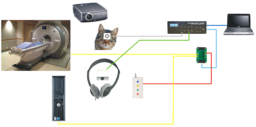
The collection of timing data and generation of responses is controlled by a second host PC/Laptop/Netbook that is connected to the BBTK v3 via USB (blue). The Digital Stimulus Capture And Response (DSCAR) module of the BBTK v3 PC software is run from this second host PC in order to detect visual stimuli, synchronization triggers and make responses with known RTs. Once the BBTK v3 has automatically stepped through your whole experiment, timing data will be presented for analysis. In addition to being able to check stimuli and synchronization timings, by comparing the RTs recorded by your experiment generator against the true RTs generated by the BBTK v3 you will also be able calculate response error. Top
All connections should be made
outside of the scanner room via a patch panel as currently we
do not advise, nor endorse, the use of any BBTK v3 sensors or
other equipment inside the scanner room. No part of the BBTK
v3 should be considered scanner safe.
Correcting timing errors
My chosen response device is adding to response timing. What should I do?
 The
first thing to do is establish the contribution the device is
adding using a BBTK v3. Once this has been established you need
to determine its variability and decide whether this is
acceptable within your current study. If the absolute error is
consistent and variability low it may be possible to subtract
the error post hoc so that RTs more closely reflect what the
true RT would have been.
The
first thing to do is establish the contribution the device is
adding using a BBTK v3. Once this has been established you need
to determine its variability and decide whether this is
acceptable within your current study. If the absolute error is
consistent and variability low it may be possible to subtract
the error post hoc so that RTs more closely reflect what the
true RT would have been.
One could measure this by telling your experiment generator to output a TTL signal/TTL trigger when presenting a stimulus. This could be used as a trigger by the BBTK v3 that would then generate a response with a known RT that could be fed into your own response device via an Active Switch Closure (ASC) lead. Alternatively the BBTK v3 Robotic Key Actuator (RKA) could be used to respond on your own response device. Detecting stimuli and responding with a known RT would be controlled by the Digital Stimulus Capture And Response (DSCAR) module of the BBTK v3 PC software. If a TTL output/TTL trigger cannot be made by the computer you are using to run the experiment you would need to examine whole system timing. To improve whole system timing accuracy you would make alterations to your experiment which tightened presentation, synchronization and response timing, e.g. by moving a visual presentation back in time to realign it with an audio stimulus.
You should bear in mind the absolute error of a response device may also affect when a stimulus presentation is terminated and the next presentation made. It could also affect synchronization between other hardware you may be using, e.g. EEG, fMRI, eye trackers etc.
Unless you are using a response box from a recognized
manufacturer reducing response timing error may mean that you
need to empirically test several different pieces of hardware
with a BBTK v3 in order to find the one with the least error,
e.g. when using keyboards as response devices. Top
How do I plot the absolute error and variability of my response device?
 Depending
on whether you used Digital Stimulus Capture And Response (DSCAR)
to generate responses, or the BBTK response pad to actively
trigger your own response device, the analysis method will vary.
If you used DSCAR you will have entered a fixed delay, i.e. RT,
which will have elapsed before a response was made. This is a
known delay and should match the response time recorded by the
experiment on the remote computer if there is zero error. To
calculate the absolute error, response times from your experiment
can be pasted into Microsoft Excel and subtracted from the true
response time. Variability in the response device can be
ascertained using standard statistical functions such as STDEV
etc.
Depending
on whether you used Digital Stimulus Capture And Response (DSCAR)
to generate responses, or the BBTK response pad to actively
trigger your own response device, the analysis method will vary.
If you used DSCAR you will have entered a fixed delay, i.e. RT,
which will have elapsed before a response was made. This is a
known delay and should match the response time recorded by the
experiment on the remote computer if there is zero error. To
calculate the absolute error, response times from your experiment
can be pasted into Microsoft Excel and subtracted from the true
response time. Variability in the response device can be
ascertained using standard statistical functions such as STDEV
etc.If you wanted to achieve a more humanistic pattern of RTs, you might have used Digital Stimulus Capture (DSC) together with the BBTK response pad and Active Switch Closure (ASC) lead tacked to the primary button of your response device. In this scenario a human participant will have responded to each stimulus, e.g. a bitmap, by pressing a response key on the BBTK response pad. Each time a key was pressed, the ASC flying lead from the pad will have simultaneously closed a button on your own response device. As each response will have been generated with a different RT this means that you will need to use the BBTK data analyser to work out the true RT for each press. This can be done using the measurement cursors or via the spreadsheet view. If using the cursor method, the first cursor should be placed on the leading edge of the stimulus event and the second on the leading edge of the pad button being pressed (assuming RTs are recorded by your experiment in relation to stimulus onsets). A response time can then be read off – you will need to do this for as many responses as you wish to analyse. In effect you have calculated each true RT – if there were zero error these should match each RT recorded by your experiment. Any difference represents the absolute error. Response times from the remote experiment can be pasted into Microsoft Excel and then subtracted from each true response time. As before, variability in your response device can be calculated using standard statistical functions such as STDEV etc. Top
I've found an error in the synchrony between my visual or auditory stimuli. How do I correct this?
 Typically
you will need to retest the paradigm using a BBTK v3 after making
incremental corrections to the stimulus onset times or durations.
For visual stimuli this may mean that you need to move a
presentation forward along the timeline and start accepting
responses earlier. If images are presented for longer than
expected you may also need to alter durations. Such corrections
may also involve various manipulations specific to the software
you are using, e.g. in E-Prime you may need to cache images using
the canvas object or alter the timing mode etc. At the most
extreme it could mean using another display device.
Typically
you will need to retest the paradigm using a BBTK v3 after making
incremental corrections to the stimulus onset times or durations.
For visual stimuli this may mean that you need to move a
presentation forward along the timeline and start accepting
responses earlier. If images are presented for longer than
expected you may also need to alter durations. Such corrections
may also involve various manipulations specific to the software
you are using, e.g. in E-Prime you may need to cache images using
the canvas object or alter the timing mode etc. At the most
extreme it could mean using another display device.Alternatively you could also manipulate the stimulus materials themselves. For example if a tone is played for longer than expected you could use a sound editor to shorten the duration so that it matched that intended when presented by the experiment generator. Another example is where you may need to insert silence into a sound files beginning to ensure that the actual sound is produced at the speakers at exactly the same point as a visual stimulus is presented.
In short you may need to move stimulus materials forward or
backwards along the experimental timeline to ensure they are
physically presented at the correct time. This can mean reducing
or elongating the durations of stimuli in what may at first seem
a counterintuitive way. You may also need to start accepting
responses earlier, or later, than initially intended. For
example, rather than time RTs from the onset of a visual
stimulus you may need to time them from the onset of a TTL
signal, or other event marker, that you initiated. If your TFT
monitor inherently has 30 ms of input lag when displaying
images, you could time RTs from 30 ms after the experiment
generator requested the image be displayed, e.g. from a TTL
event marker. In this example the 30 ms correction would realign
the stimulus in terms of what physically happened in the real
world and the timings the experiment generator subsequently
recorded. Once you have used a BBTK to empirically discover the
direction and scale of timing errors you are in a much better
position to make such corrections. Top
There is a synchronisation error between my experiment and third party equipment (EEG, MEG, fMRI, eye tracker). How do I correct this?
 If
you are presenting stimuli based on a TTL sync signal/TTL
trigger from third party equipment such as EEG, MEG, fMRI, eye
tracker etc, it may be that your experiment generator reacts to
it later than intended. For example, TFT input lag may mean that
a stimulus image is displayed 50 ms later than the sync signal
is sent. Through previous testing you may have established that
the input lag of your particular TFT monitor is 30 ms. In this
case the additional 20 ms would be likely to be caused by delays
within the experiment generator and/or computer system. To
correct the late display relative to the sync signal you would
need to move the signal forward by 50 ms in time so that the
visual presentation was correctly aligned in the real world.
Typically this would need to be done in the equipment generating
the sync signal. On some occasions the 50 ms delay may still
exist, but simply be timeshifted forward by 50 ms.
If
you are presenting stimuli based on a TTL sync signal/TTL
trigger from third party equipment such as EEG, MEG, fMRI, eye
tracker etc, it may be that your experiment generator reacts to
it later than intended. For example, TFT input lag may mean that
a stimulus image is displayed 50 ms later than the sync signal
is sent. Through previous testing you may have established that
the input lag of your particular TFT monitor is 30 ms. In this
case the additional 20 ms would be likely to be caused by delays
within the experiment generator and/or computer system. To
correct the late display relative to the sync signal you would
need to move the signal forward by 50 ms in time so that the
visual presentation was correctly aligned in the real world.
Typically this would need to be done in the equipment generating
the sync signal. On some occasions the 50 ms delay may still
exist, but simply be timeshifted forward by 50 ms.
To correct a timeshifted delay you may need to send two TTL sync signals/TTL triggers from your equipment where the first is a "dummy signal" that is used to trigger the experiment generator to display the image and the second is the real sync signal, i.e. 50 ms later to correct for the error described above. You would need to program your experiment generator to display the image on the first and time RTs from the second signal. This would temporally align the display of the image with the "real" sync signal, i.e. the second one.
On the other hand if there is a consistent timing error
relative to a regular reference pulse, e.g. as in fMRI, you may
need to temporally realign the signal itself. This may mean
altering the frequency or duration of the pulse. To do this you
should consult the reference guides for the equipment that is
generating the signal and the experiment generator you are
using. Top
Should I look at whole system timing to improve my accuracy?
 The
short answer is yes! Whole system timing is where you consider
the timing accuracy of everything as a cohesive unit. By
"system" we mean your computer and operating system, your
presentation devices, response devices and any other third party
hardware you interact with, e.g. EEG, MEG, fMRI, eye trackers
etc.
The
short answer is yes! Whole system timing is where you consider
the timing accuracy of everything as a cohesive unit. By
"system" we mean your computer and operating system, your
presentation devices, response devices and any other third party
hardware you interact with, e.g. EEG, MEG, fMRI, eye trackers
etc.
This means that you need to use a BBTK v3 to evaluate every aspect of your timing, i.e. presentation, synchronisation and response. Once you have a set of baseline timings you should then make small incremental changes that lead to improvements in accuracy when measured empirically with a BBTK. This may on occasion mean that you need to make adjustments that at first seem counterintuitive. For example, by reducing the length of a sound file so that it plays for the correct duration on your specific sound card, amplifier and speakers, or by playing it earlier to realign it with a visual stimulus.
You may also need to apply some lateral thinking to improve your timing. This could mean rather than timing responses from the onset of a stimulus image, to time RTs from a "phantom" TTL pulse you generate 30 ms later to account for a 30 ms input lag in the TFT you are using. It could also mean that you need to reconfigure any third party equipment to work in a slightly different way. For example, to modify the way it sends sync signals/TTL triggers to, or from, your equipment in terms of pulse frequency, duration or number. It can also mean that you need to change some of the equipment you are using, e.g. a specific keyboard or mouse. At the most extreme it can mean that you may need to consider using a different experiment generator or modifying your own code. It is now accepted that different experiment generators may be more suited to some research areas than others. Top
What's the best X? – The Curate's Egg*
What's the most accurate experiment generator for presentation and response timing?
Some experiment generators are strong in one area and weak in
others. In an ideal world one might consider using a mix of
experiment generators and custom written software. However to
discover in which areas a particular piece of software is strong
you will need to use the Black Box ToolKit v3 to confirm this.
In addition you should bear in mind that the same piece of
software can perform very differently on two computer systems.
Again this is a prerequisite for using the Black Box ToolKit. Top
Which brand/model or computer is the most accurate?
 Unfortunately
all computer systems vary in terms of their timing accuracy. This
means it is impossible to identify a single "best system" as there
are so many variables that need to be considered. Manufacturers
typically change the components they build into computer systems
on a batch-by-batch or month-by-month basis which makes it hard to
recommend one brand or model over another. In effect you should
consider computer systems as being commodity items. Two identical
looking systems may actually be very different internally and have
different levels of timing accuracy as timing accuracy is often
tied to the hardware. The way the operating system is configured
can also have an affect, as can installed software, drivers and
virus checkers which is why you should use a Black Box ToolKit v3
to check your own timing accuracy. Top
Unfortunately
all computer systems vary in terms of their timing accuracy. This
means it is impossible to identify a single "best system" as there
are so many variables that need to be considered. Manufacturers
typically change the components they build into computer systems
on a batch-by-batch or month-by-month basis which makes it hard to
recommend one brand or model over another. In effect you should
consider computer systems as being commodity items. Two identical
looking systems may actually be very different internally and have
different levels of timing accuracy as timing accuracy is often
tied to the hardware. The way the operating system is configured
can also have an affect, as can installed software, drivers and
virus checkers which is why you should use a Black Box ToolKit v3
to check your own timing accuracy. TopWhat's best for visual presentation: a CRT, TFT or data projector?
 Depending
on the context you wish to use the display device in and the
paradigm in question, the balance varies. For example, for RSVP
and priming or experiments where synchronisation is important, the
only realistic option remains a CRT. In general data projectors
have the worst input lag, with TFTs somewhere in the middle. Input
lag means that images are not displayed when requested as the
display devices electronics takes time to process the image and
physically display it. Unfortunately an experiment generator only
knows about the time it requested the image be displayed and not
when it physically appeared on-screen.
Depending
on the context you wish to use the display device in and the
paradigm in question, the balance varies. For example, for RSVP
and priming or experiments where synchronisation is important, the
only realistic option remains a CRT. In general data projectors
have the worst input lag, with TFTs somewhere in the middle. Input
lag means that images are not displayed when requested as the
display devices electronics takes time to process the image and
physically display it. Unfortunately an experiment generator only
knows about the time it requested the image be displayed and not
when it physically appeared on-screen.
In general researchers should be aware of the mechanics of how
different types of displays work and their likely impact on
timing accuracy. By using a Black Box ToolKit v3 you can help
ensure that the timing characteristics of your own specific
display device is accounted for. We appreciate that CRT displays
are not always available, or practicable, and so there may be
mitigating circumstances for using devices with inferior timing
characteristics. Top
What's the best response device?
 Depending
on the experiment you are running you may be limited in your
choice of response device. Ideally you should use a recognized
manufacturers response box, or pad like those available from
ourselves, as this is likely to have a small internal delay
that contributes relatively little to response time error.
However, it is worth bearing in mind some computer mice can have
an equal, or better variability, as compared with some experiment
generator vendors own devices. Combined with a small absolute
error such mice can offer a viable alternative, which can cost
many hundreds of times less in some cases.
Depending
on the experiment you are running you may be limited in your
choice of response device. Ideally you should use a recognized
manufacturers response box, or pad like those available from
ourselves, as this is likely to have a small internal delay
that contributes relatively little to response time error.
However, it is worth bearing in mind some computer mice can have
an equal, or better variability, as compared with some experiment
generator vendors own devices. Combined with a small absolute
error such mice can offer a viable alternative, which can cost
many hundreds of times less in some cases.Typically much of the inaccuracy response devices contribute to RTs is due to inherent delays within the hardware itself. For example a typical keyboard can add approximately 30~70ms to the true RT. Much of this variability is due to a scanning, or polling loop, where key states are checked and then reported to the computer. Any response device which has buttons, or keys, that need to be checked or its position monitored, e.g. a computer mouse, will most likely make use of polling loops and have an inbuilt level of absolute error and variability.
You should bear in mind that manufacturers' of input devices,
e.g. mice, keyboards, sound cards are under no obligation to
make them millisecond accurate. So long as they work as intended
and are electrically safe they are suitable for sale. The online
gaming community are quite fanatical about mice, as for them
fast responses are important and can give them a competitive
edge. A Google search for "fastest mouse response for gaming"
will give you a good insight into timing characteristics of
widely available mice. However, you should bear in mind that
manufacturers are liable to change components within input
devices even though they may look the same externally. As a
result you are advised to test the timing accuracy of your own
response devices using a Black Box ToolKit v3. Top
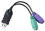
I can connect my response device by either USB, PS/2 or serial. What interface is best?
 Research
has shown that although interfaces differ in transfer speed the
actual response accuracy is largely determined by the response
hardware itself and not the bandwidth of the connection to the
computer. That is, how quickly the devices internal microcode
scans for button, or key presses, in a polling loop. This is
illustrated by the fact that a mouse that offers both USB and PS/2
interfaces actually changes response characteristics when the
interface is changed. Simply by swapping the interface, two
different pieces of microcode are used. Each has its own timing
characteristics independent of the type of connection to the
computer. As a result response devices should be checked
independently using a Black Box ToolKit v3 to ascertain their
contribution to timing error. You should also be wary of
convertors which offer serial to USB interface conversion as often
they can add an unknown contribution to timing. Top
Research
has shown that although interfaces differ in transfer speed the
actual response accuracy is largely determined by the response
hardware itself and not the bandwidth of the connection to the
computer. That is, how quickly the devices internal microcode
scans for button, or key presses, in a polling loop. This is
illustrated by the fact that a mouse that offers both USB and PS/2
interfaces actually changes response characteristics when the
interface is changed. Simply by swapping the interface, two
different pieces of microcode are used. Each has its own timing
characteristics independent of the type of connection to the
computer. As a result response devices should be checked
independently using a Black Box ToolKit v3 to ascertain their
contribution to timing error. You should also be wary of
convertors which offer serial to USB interface conversion as often
they can add an unknown contribution to timing. TopPC/MAC/Linux... Which is best?
 As
is the case with experiment generators one cannot recommend one
platform over another as each has its own specific strengths and
weaknesses. Most modern operating systems are multitasking and
therefore the inherent risk of inaccurate timing is always a
possibility. As timing inaccuracy is caused by a combination of
hardware and software interaction making any generalisable
prediction as to accuracy impossible. Top
As
is the case with experiment generators one cannot recommend one
platform over another as each has its own specific strengths and
weaknesses. Most modern operating systems are multitasking and
therefore the inherent risk of inaccurate timing is always a
possibility. As timing inaccuracy is caused by a combination of
hardware and software interaction making any generalisable
prediction as to accuracy impossible. TopSoundcards... Which one should I buy?
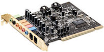 All
soundcards are susceptible to soundcard startup latency. This is
the time it takes a sound to physically emerge at the speakers
versus the time the computer requests the sound be played.
Generally more expensive soundcards have lower startup latencies
as compared with those that are integrated within a computers
motherboard, e.g. AC97 or Intel High Definition Audio (also called
HD Audio or Azalia). Typically cards that offer ASIO drivers have
better quality hardware and drivers and therefore tend to have
lower startup latencies. To be certain of the contribution your
soundcard is making to audio presentation delays you will need to
check startup latencies using a Black Box ToolKit v3.
All
soundcards are susceptible to soundcard startup latency. This is
the time it takes a sound to physically emerge at the speakers
versus the time the computer requests the sound be played.
Generally more expensive soundcards have lower startup latencies
as compared with those that are integrated within a computers
motherboard, e.g. AC97 or Intel High Definition Audio (also called
HD Audio or Azalia). Typically cards that offer ASIO drivers have
better quality hardware and drivers and therefore tend to have
lower startup latencies. To be certain of the contribution your
soundcard is making to audio presentation delays you will need to
check startup latencies using a Black Box ToolKit v3.For computer based musicians soundcard latencies are crucial. A
Google search for "sound card startup latency" will help you
identify inherently fast cards. For an acceptable "feel" when
playing a sound, the latency should be in the range of 10 ms or
lower. Unfortunately most soundcards have much higher latencies,
which can be as high as several hundred milliseconds. Top
Which graphics card?
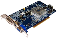 Typically
all cards that support Microsoft DirectX should be capable of
very fast display/buffering times. However you should bear in
mind that some drivers are better than others. Once you have
checked a paradigm with the Black Box Toolkit v3 you are advised
not to update any system drivers without retesting. In addition
some drivers offer advanced options such as tick boxes that
allow you to sync the card with the refresh signal, e.g. ATI's
Catalyst drivers. Various settings can alter display performance
and should be checked if you have problems. You are advised to
consult various gaming websites as again display performance is
crucial for gamers.
Typically
all cards that support Microsoft DirectX should be capable of
very fast display/buffering times. However you should bear in
mind that some drivers are better than others. Once you have
checked a paradigm with the Black Box Toolkit v3 you are advised
not to update any system drivers without retesting. In addition
some drivers offer advanced options such as tick boxes that
allow you to sync the card with the refresh signal, e.g. ATI's
Catalyst drivers. Various settings can alter display performance
and should be checked if you have problems. You are advised to
consult various gaming websites as again display performance is
crucial for gamers.
A Google search for ��fast graphics card for gaming�� will help
you identify good cards and those with known problems. Top
Are faster multi-core processors better than slower ones?
 Not
necessarily as there are no guarantees that a faster system
doesn't have other "issues" that prevent accurate timing. For
example drivers, add-in cards, installed software, background
tasks and the like will have an affect on your ability to obtain
millisecond accurate presentation, synchronisation and response
timings. Computers that have a faster GHz rating don't necessarily
have more accurate clocks. To find out more about clock drift
Google "PC clock drift". Some PCs' clocks can gain over 10 minutes
per day whilst others loose time. This is due to the quality of
the crystal oscillator on the motherboard and it is this that
provides a base for all millisecond timing.
Not
necessarily as there are no guarantees that a faster system
doesn't have other "issues" that prevent accurate timing. For
example drivers, add-in cards, installed software, background
tasks and the like will have an affect on your ability to obtain
millisecond accurate presentation, synchronisation and response
timings. Computers that have a faster GHz rating don't necessarily
have more accurate clocks. To find out more about clock drift
Google "PC clock drift". Some PCs' clocks can gain over 10 minutes
per day whilst others loose time. This is due to the quality of
the crystal oscillator on the motherboard and it is this that
provides a base for all millisecond timing.In addition use of multi-core processors with, or without
Hyper-Threading, does not automatically mean that timing will be
any better. In fact, many multi-core systems actually perform
worse than equivalently clocked single core systems. Remember
the vast majority of software is not optimised to run on
multi-core, or Hyper-Threaded, systems. Top
*What does the term "Curate's Egg" mean?
 A
curate is a term used in various Christian religions who possess
an ordained ministry to describe a priest who is not a parish
priest but operates in effect as his or her deputy. Some larger
parishes may have more than one curate. Most curates are
eventually raised to become a parish priest in another parish as
the older priests retire or die.
A
curate is a term used in various Christian religions who possess
an ordained ministry to describe a priest who is not a parish
priest but operates in effect as his or her deputy. Some larger
parishes may have more than one curate. Most curates are
eventually raised to become a parish priest in another parish as
the older priests retire or die.The expression "a curate's egg" meaning something that is partly good and partly bad and thus not wholly satisfactory, arises from the publication of a cartoon in Punch on 9 November 1895. The cartoon, drawn by George du Maurier and entitled, "True Humility", featured a timid looking curate taking breakfast in his bishop's house. The bishop says, "I'm afraid you've got a bad egg, Mr Jones". Apparently trying not to cause offence the curate replies, "Oh, no, my Lord, I assure you that parts of it are excellent!". https://en.wikipedia.org/wiki/Curate's_egg Top
Technical
How does the Black Box ToolKit v3 connect to the host PC?
 The
BBTK connects to a standard Microsoft Windows XP, 7, 8 or
Windows 10 (32 or 64 bit) machine via a USB 2 or 3 port. This
host PC controls the BBTK v3 and is used to analyse timing data
once collected from the remote system. If you are making use of
the API you can control the BBTK v3 from any system that
supports the serial protocol over USB, e.g. Mac, Linux etc. Top
The
BBTK connects to a standard Microsoft Windows XP, 7, 8 or
Windows 10 (32 or 64 bit) machine via a USB 2 or 3 port. This
host PC controls the BBTK v3 and is used to analyse timing data
once collected from the remote system. If you are making use of
the API you can control the BBTK v3 from any system that
supports the serial protocol over USB, e.g. Mac, Linux etc. Top
What's the difference between Passive and Active Switch Closure?
Passive Switch Closure is where a flying lead from your response device switch is fed into the BBTKv3 . So when you press a button on your response device its timing characteristics are also recorded by the BBTK v3 at the same time as your own experiment (response onset and duration are recorded).Active Switch Closure is where a flying lead is attached to your response device switch from the BBTK v3. BBTK v3 applications such as DSCAR (Digital Stimulus Capture And Response) can then close the switch of your response device as if it had been pressed by a human participant once a stimulus was detected. Top
Environmental considerations
 When
using the opto-detectors you are advised to work in a room
illuminated by natural lighting. Artificial fluorescent lighting
for example can inadvertently activate the sensitive
opto-detectors. Typically this will appear as mains frequency
hum when you analyse your data (regular spaced peaks at
50/60Hz).
When
using the opto-detectors you are advised to work in a room
illuminated by natural lighting. Artificial fluorescent lighting
for example can inadvertently activate the sensitive
opto-detectors. Typically this will appear as mains frequency
hum when you analyse your data (regular spaced peaks at
50/60Hz).
Indirect artificial lighting is generally suitable or as an
alternative mask out the back of the polycarbonate opto-detector
with opaque tape. Top
Will your kit work in our MRI scanner room?
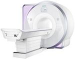 Currently
no parts of the BBTK v3, or any other of our products (unless
specifically marked), should be considered scanner safe. To
utilise the BBTK v3 you are advised to make use of a patch panel
and tap into sync signals/TTL triggers, video I/O, audio,
responses etc. from there.
Currently
no parts of the BBTK v3, or any other of our products (unless
specifically marked), should be considered scanner safe. To
utilise the BBTK v3 you are advised to make use of a patch panel
and tap into sync signals/TTL triggers, video I/O, audio,
responses etc. from there.
It is likely that it will be possible to check the timing accuracy of presentation and response equipment outside of the scanner room, e.g. data projectors, headphones, response pads etc, whilst running the identical paradigm. Top
Is there a Mac version of the software? Is there an API?
Currently we only supply our BBTK v3 control and analysis software as a Microsoft Windows application. However, you can use the BBTK v3 API to control and analyse data using any platform that supports the standard ASCII/text protocol over serial. The BBTK v3 is physically connected by USB but is accessed via a virtualised serial COM port. This means that you can control the BBTK v3 from MATLAB, PsychoPy or any other software, or platform, that supports a COM port, e.g. Mac, Linux etc.
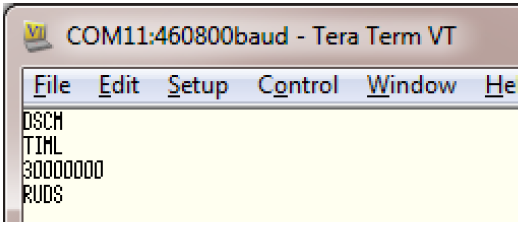 |
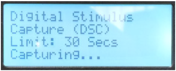 |
The BBTK v3 itself is controlled using simple four letter commands and line change event data/time stamps are streamed back after a testing session has reached a set time limit. The serial terminal example above shows four commands that instruct the BBTK to capture events across any of its input channels and then upload data after 30 seconds. The LCD screen of the BBTK v3 s shown for reference. A printed API user guide is supplied with certain models. Alternatively this can be purchased as an option item with any model. Top
We've built some custom response equipment. How do we link to the TTL interfaces/TTL triggers offered by the BBTK v3?
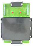 To
make use of the BBTK v3 TTL I/O interface you need to be able to
generate TTL signals/TTL triggers that present 0V to 3~5V
signals. Where the change from 0 to 3~5V indicates a change in
activity, e.g. MRI scanner sync pulse, visual stimulus image
onset etc. In addition the BBTK v3 can generate TTL signals/TTL
triggers in order to event mark activity or stimuli onset, e.g.
conditional EEG event marking, simultaneous TTL signal with a
response action such as an Active Switch Closure (where a
response key is closed on your own device).
To
make use of the BBTK v3 TTL I/O interface you need to be able to
generate TTL signals/TTL triggers that present 0V to 3~5V
signals. Where the change from 0 to 3~5V indicates a change in
activity, e.g. MRI scanner sync pulse, visual stimulus image
onset etc. In addition the BBTK v3 can generate TTL signals/TTL
triggers in order to event mark activity or stimuli onset, e.g.
conditional EEG event marking, simultaneous TTL signal with a
response action such as an Active Switch Closure (where a
response key is closed on your own device).
Depending on which version of the BBTK v3 you purchased it will have between two and 20 TTL I/O lines. To increase the number of TTL lines/TTL triggers available an expansion pack offering an additional 16 TTL lines can be used with any BBTK (ships with the Elite by default). Top
How many screen regions can I monitor at once?
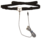 The
Entry level BBTK v3 can make use of a maximum of two
opto-detectors, and the Pro and Elite four. By default they ship
with one, two and four opto-detectors respectively. Opto-detectors
can be used with TFTs, CRTs, data projectors or any other device
that switches between no, or little light/black, and bright light,
i.e. black and white event markers.
The
Entry level BBTK v3 can make use of a maximum of two
opto-detectors, and the Pro and Elite four. By default they ship
with one, two and four opto-detectors respectively. Opto-detectors
can be used with TFTs, CRTs, data projectors or any other device
that switches between no, or little light/black, and bright light,
i.e. black and white event markers.The BBTK v3 Elite allows you to monitor up to four separate
regions simultaneously. You can instruct the BBTK v3 to trigger
a response when it detects activity on one or more
otpo-detectors. Alternatively it can conditionally event mark
based on logic you predefine, e.g. conditional event marking
using TTL signals/channels on an EEG trace. Top
How do I adjust the sensitivity of the Black Box ToolKits v3 sensors?
The sensitivity of the BBTK v3 sensors, e.g. opto-detectors, mics etc. are digitally adjusted and range between 0~127. In general they should be adjusted in line with the performance characteristics of a human. Simply, place the sensors where you'd expect a human to be looking or listening. Then using the Sensor Threshold Manager (STM) to adjust the sensitivity via the rotary encoder (turn and push knob) on the front panel of the BBTK v3 until the activity lights illuminate and dim when the stimulus is removed. As threshold values change a digital value will be simultaneously displayed on the BBTK v3 LCD and in our PC software.
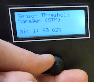 |
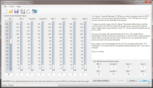 |
Digital thresholds for each sensor can be saved and recalled at any time. To help aid consistency, the current sensor threshold values are saved with timing data files. If you are using the BBTK v3 with your own software, via the BBTK v3 API, you can read and set sensor thresholds individually when required. Top
Can I use the kit with third party experiment generators or software I wrote myself?
Yes. You can use the BBTK v3 API to control and analyze data using any platform that supports the standard ASCII/text protocol over serial. The BBTK v3 is physically connected by USB but is accessed via a virtualised serial COM port. This means that you can control the BBTK v3 from MATLAB, PsychoPy or any other software, or platform, that supports a COM port, e.g. Mac, Linux etc.
The BBTK v3 itself is controlled using simple four letter commands and line change event data/time stamps are streamed back after a testing session has reached a set time limit. The serial terminal example below shows four commands that instruct the BBTK v3 to capture events across any of its input channels and then upload data after 30 seconds. The LCD screen of the BBTK v3 is shown for reference. A printed API user guide is supplied with certain models. Alternatively this can be purchased as an option item with any model. Top
How do I link the BBTK v3 up to my MRI scanner sync pulse so that I can relate presentations to actual acquisitions?
The kit provides up to 10 TTL input lines (3.3~5V). Any of these can be used to track the scanner sync pulse. You are advised to alter your scanner sync pulse characteristics so that it is long enough to be detected by the BBTK v3 and easily seen by you within a timing validation run, e.g. 10-20 ms width, high active.When you assess the timing accuracy of your experiment you will also capture the scanner sync pulse as well as visual and auditory presentations and subsequent responses. In the 20 channel logic analyzer you will be able to see the relationship between the scanner sync pulse, visual and auditory presentations and any responses. With this additional data you should be able to correlate brain activity on any given acquisition with a specific presentation and subsequent response data.
The BBTK v3 can also feed TTL signals/TTL triggers back into your scanner software in order to provide event markers for stimulus, synchronization or response events. Up to 10 TTL output lines are available for this purpose. Top
Bench test equipment comparisons
Can I use the Black Box ToolKit v3 like a traditional digital oscilloscope?
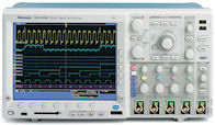 No.
The BBTK v3 only supports binary states on each input and output
line, either on or off, TTL +3~5V and 0V, or switch closure
active or not active.
No.
The BBTK v3 only supports binary states on each input and output
line, either on or off, TTL +3~5V and 0V, or switch closure
active or not active.
In addition there is no live moving graphical display as with a traditional oscilloscope. Instead data is analyzed graphically once collected. You can think of the BBTK as offering the same functionality as a binary state 36 channel digital oscilloscope or logic analyzer. Top
Can I use the Black Box ToolKit v3 like a traditional pulse/function generator?
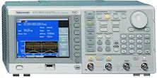 Yes.
However the BBTK v3 only supports binary states on each output
line as a square wave, TTL +3~5V and 0V, or switch closure active
or not active. Whereas traditional function generators let you
create different forms of waves and also vary the voltage. The
BBTK v3 enables you to create an infinite number of regular square
wave TTL events across up to 36 channels.
Yes.
However the BBTK v3 only supports binary states on each output
line as a square wave, TTL +3~5V and 0V, or switch closure active
or not active. Whereas traditional function generators let you
create different forms of waves and also vary the voltage. The
BBTK v3 enables you to create an infinite number of regular square
wave TTL events across up to 36 channels.In some respects the function generation part of the BBTK v3 is
more advanced than a traditional device. For example, each event
can have any onset and pulse width and events can occur on any
line or channel. Traditional function generators do not allow
you to vary onsets and widths on an event-by-event basis. Top
Can I do what the Black Box ToolKit v3 does with a digital oscilloscope and signal generator?
 No.
In effect you would need a 20 channel digital oscilloscope/logic
analyzer to monitor inputs and a 16 channel function generator to
generate responses. This type of setup would be prohibitively
expensive and would mean that several devices would need to be
daisy chained together to achieve the same number of channels. In
addition making the oscilloscope/logic analyzer talk to the
function generator on an event-by-event basis would be extremely
difficult, if not impossible, as such equipment is not designed to
work in this way. Remember the BBTK v3 can respond on an
event-by-event basis to stimuli and generate patterns of responses
as if it were a human participant. All parameters can be set
quickly and easily and results are displayed graphically in 20
channel logic analyzer. Each event onset, offset and duration is
simultaneously displayed in spreadsheet windows for rapid
analysis.
No.
In effect you would need a 20 channel digital oscilloscope/logic
analyzer to monitor inputs and a 16 channel function generator to
generate responses. This type of setup would be prohibitively
expensive and would mean that several devices would need to be
daisy chained together to achieve the same number of channels. In
addition making the oscilloscope/logic analyzer talk to the
function generator on an event-by-event basis would be extremely
difficult, if not impossible, as such equipment is not designed to
work in this way. Remember the BBTK v3 can respond on an
event-by-event basis to stimuli and generate patterns of responses
as if it were a human participant. All parameters can be set
quickly and easily and results are displayed graphically in 20
channel logic analyzer. Each event onset, offset and duration is
simultaneously displayed in spreadsheet windows for rapid
analysis.The BBTK v3 also allows you to respond in different ways to
different stimulus patterns, plus the characteristics of each
response itself can be altered on an event-by-event basis. The
complexity of using standard oscilloscopes and function
generators together is simply too great an overhead as compared
with the simple graphical interface of the BBTK v3. Top
What's the typical sampling rate of the Black Box Toolkit v3?
When compared to bench equipment the kit samples at relatively low rates. Although the ARM chip in the BBTK v3 runs with a clock speed of 96 MHz (96 million instructions per second) we have chosen to downsample to 6 kHz on a highly precise interrupt driven basis. The external crystal clock that we use for timestamping data is running with nanosecond precision.This is because unlike bench equipment the BBTK v3 allows you to replay all event data captured over periods of many minutes using its 8 MB of internal RAM. Digital oscilloscopes/logic analyzers sample at much higher rates but can only replay events over a very short period, e.g. a second or two, and across many less channels, e.g. 2 to 4 channels for a typical oscilloscope/logic analyzer.
By sampling at 6 kHz this gives us enough accuracy to be
confident we are measuring and generating events with
sub-millisecond accuracy, i.e. six samples per millisecond
across 36 channels. The graphical 20 channel logic analyzer lets
you zoom in to compare any two or more events at the millisecond
level whereas the raw data spreadsheets report the same events
with sub-millisecond precision. Because the BBTK v3 runs
independently of the PC and has its own CPU and external crystal
clock, you can be sure of its accuracy. Top
Training, demos & consultancy services
Our department would like you to come and give a talk. Would you be willing to do this?
 Yes.
As standard we charge a daily rate plus expenses. Talks and
visits typically include a grounding in the academic timing
literature, a live demo of the Black Box ToolKit v3 or any of
our other products, a Q & A session and an interactive forum
where we can advise on your specific paradigms.
Yes.
As standard we charge a daily rate plus expenses. Talks and
visits typically include a grounding in the academic timing
literature, a live demo of the Black Box ToolKit v3 or any of
our other products, a Q & A session and an interactive forum
where we can advise on your specific paradigms.
Please feel free to contact us to discuss your requirements. Top
We'd like to integrate some best practice guidance into the way we teach undergraduates in the use of experiment generators. Could you advise us?
Yes. Typically we help construct high quality teaching materials that can be delivered to students during research methods courses. There are worked examples with common experiment generators and resources which highlight potential sources of error and workable solutions. As part of the experience we favour one onsite visit where we can demonstrate errors and take part in Q & A sessions with students. Please feel free to contact us to discuss your requirements. TopOur study is time critical and we need to have validated results together with independent timing certification. Do you offer a consultancy service?
 Yes.
We offer a service whereby we can visit onsite to test your
specific equipment and paradigm. Alternatively we can test your
software or hardware in our lab on calibrated computer systems and
tablets. Whether we test onsite or in our own lab, either option
will result in an independent timing certification report and
detailed advice on how to improve your accuracy.
Yes.
We offer a service whereby we can visit onsite to test your
specific equipment and paradigm. Alternatively we can test your
software or hardware in our lab on calibrated computer systems and
tablets. Whether we test onsite or in our own lab, either option
will result in an independent timing certification report and
detailed advice on how to improve your accuracy.As part of our ongoing dedication to improving timing accuracy across the field we also offer a cost-effective in-house hardware design and build service. This means we can help provide hardware for custom applications that require accurate timing. Please feel free to contact us to discuss your requirements. Top
Contact us & ordering
How do I order?
 The
first step in the process is to request a formal quotation. This
is valid for 30 days and prices are tied to Pounds Sterling
(GBP) as we are based in the UK. We will convert prices to your
local currency based on the date the quote was issued. Each
quote will also include worldwide shipping and insurance as
standard. If you need to discuss your requirements in more depth
we will be happy to help.
The
first step in the process is to request a formal quotation. This
is valid for 30 days and prices are tied to Pounds Sterling
(GBP) as we are based in the UK. We will convert prices to your
local currency based on the date the quote was issued. Each
quote will also include worldwide shipping and insurance as
standard. If you need to discuss your requirements in more depth
we will be happy to help.
If you decide to place an order we will require an official
Purchase Order with EU VAT number if applicable. Next we will
usually invoice you on a Pro Forma basis, i.e. payment in
advance, as the majority of our sales are outside the UK. Once
we receive cleared payment shipping is usually within five
working days. All shipments are dispatched using a fully tracked
signed for service. Top
Do you offer multi-pack discounts?
Yes. We have priced all Black Box Toolkit products very competitively in terms of the functionality they offer. For example the Black Box ToolKit v3 is priced at approximately the equivalent cost of a mid to high-end laptop and we hope that organizations that are serious about the quality of their science will purchase a Black Box ToolKit v3 for each of their research groups. For individual quotes please contact us directly. Top
I need to talk specifics
If you need to talk about the functionality of our products you should talk to us directly and we will be glad to advise based on your query. Please note we are unable to give specific advice on timing issues unless you are one of our existing customers as this will count as technical support. Top